What We Do
Underground
Advanced trenchless technology and ground improvement — from 400mm HDD crossings to 3,500mm mega-diameter micro-tunneling — anywhere across the Kingdom.

Micro Tunneling
STCO has massively invested in the most sophisticated Micro Tunneling (MT) technology from Germany. This technology allows construction of accurate subsurface installations of Steel or Reinforced Concrete Pipes in various sizes in any soil conditions with a minimum disruption to surface facilities and within minimum time frame.
Micro Tunneling technology is approved worldwide as the most effective and safest procedure in the utility construction industry and is preferred over the traditional open-cut approach — not only under highways but also in populated urban areas.
Utilizing advanced AVN systems for high-precision pipe jacking, capable of handling diameters from 800mm to 3,500mm in challenging geological conditions.
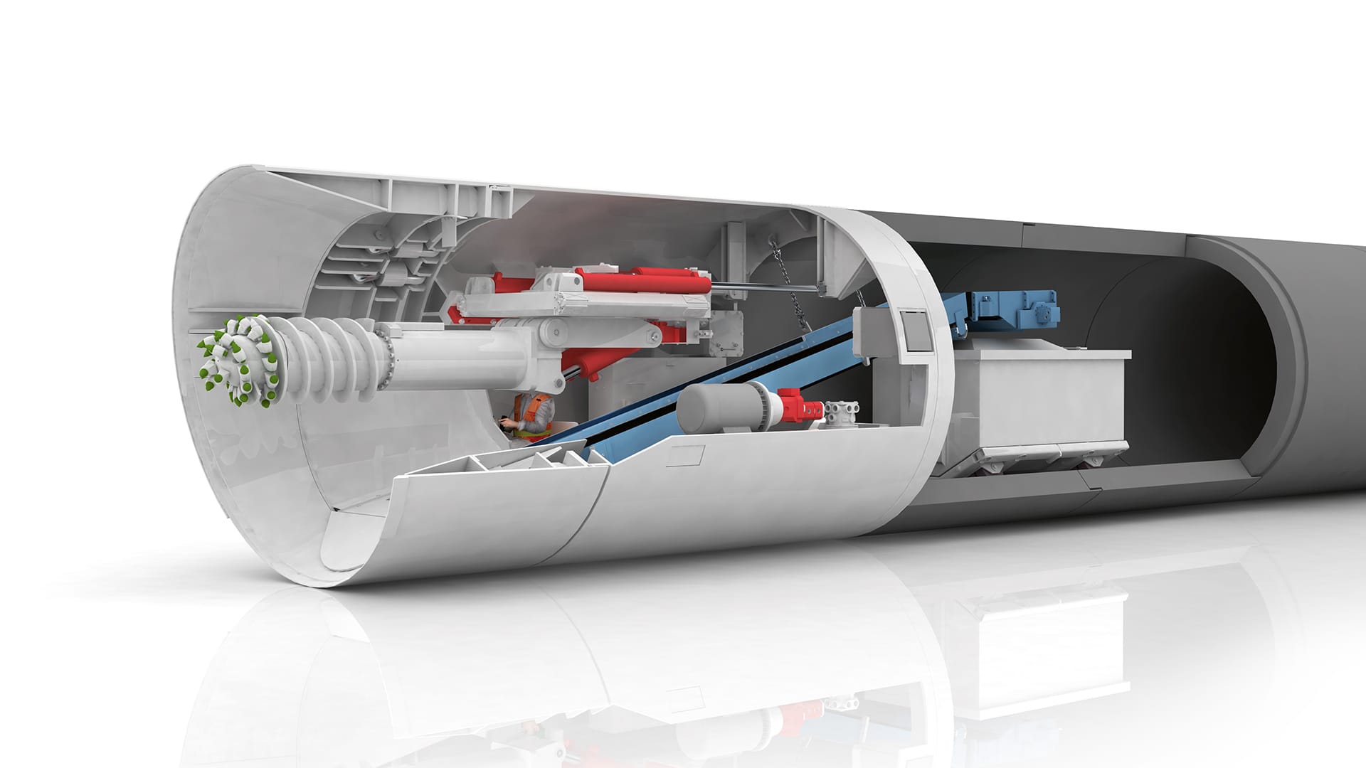
Micro Tunnel Machine Works
The AVN pipe-jacking system is a remote-controlled, laser-guided process that bores through the ground while simultaneously installing the permanent pipe.
Shaft Preparation
Launching and receiving shafts are excavated and structurally prepared as the entry and exit points for the tunneling machine.
Machine Launch
The AVN shield machine is lowered into the launching shaft and set on the guide frame aligned to the designed bore profile.
Pipe Jacking
The main jacking station pushes the pipe string forward while the cutting head excavates. Intermediate jacking stations manage long drives and friction loads.
Machine Recovery
Upon completing the crossing, the machine head is recovered at the receiving shaft. The installed pipe is then connected and commissioned.
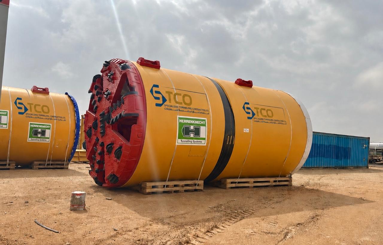
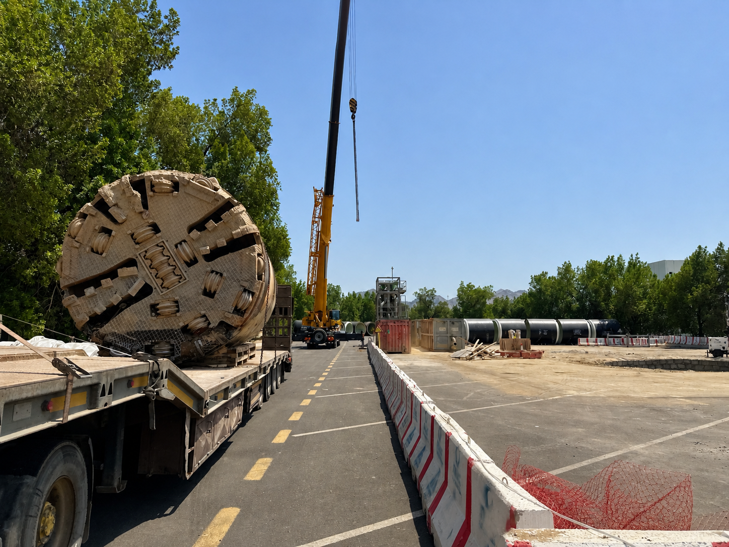
AVN Machine Fleet
STCO owns and operates a full fleet of AVN micro-tunneling machines from 800mm to 3,500mm — including D-mode upsizing capability on the largest units.
AVN3000
Up to 3,500mm with D-mode upsizing system
AVN2200
Up to 2,800mm with D-mode upsizing system
AVN1600
Up to 1,800mm
AVN1200
Up to 1,400mm
AVN800
Up to 1,000mm
Separation Plant
Full bentonite slurry separation and treatment
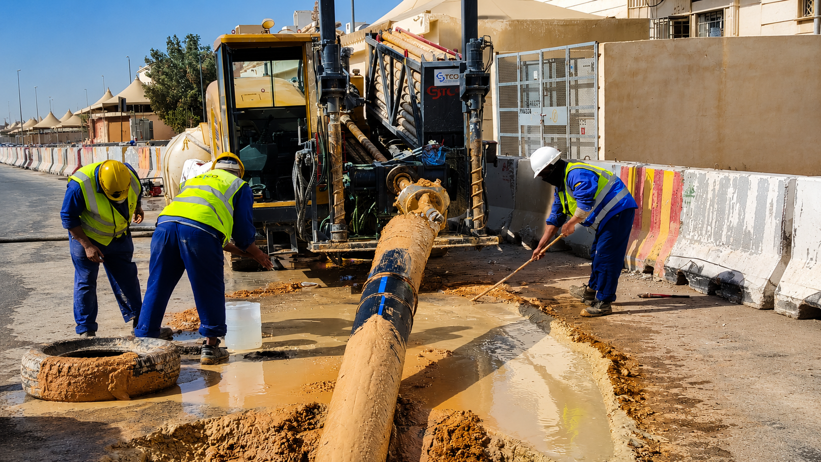
Horizontal Directional Drilling
To fulfil the growing markets of the telecommunication industry in the Gulf Region and complement pipelining projects, STCO has acquired Horizontal Directional Drilling (HDD) capabilities. After a careful analysis of market requirements and technology screening, STCO invested in medium-size HDD setups that allow subsurface installation of flexible pipes for gas, water, telecommunication, and environmental crossings.
Being supported by directionally controlled mud motors and advanced cutting tools of the oil & gas drilling industry, HDD offers versatile, non-intrusive installations for pipelines and conduits up to 1200mm in diameter.
HDD Machine Works
The HDD process follows three precise phases to install the product pipe without surface excavation.
Pilot Hole
A small-diameter pilot hole is drilled along the designed bore profile using a directionally controlled drill string guided by a survey tool. Wash pipe, pilot string, and drill profile are precisely set using the bottom hole assembly (BHA) with a bent motor housing and angular offset bit.
Pre-Reaming
The pilot hole is enlarged to the required diameter by pulling a reamer back through it. The wash pipe and reamer expand the bore progressively, ensuring the annular space is sufficient for the product pipe's installation without collapse.
Pull-Back
The product pipe is attached via a swivel to the reamer and pulled back through the borehole as final reaming is completed. The reamer swivel prevents torque transfer to the product pipe, ensuring its structural integrity during installation.
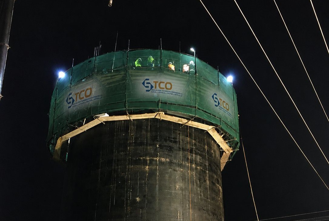
Shaft Works
Shafts are the doors to the underground — their design and construction are key to the successful completion of any tunneling project. Each tunnel requires two shafts: a Launching Shaft and a Receiving Shaft.
Launching Shaft: Mainly used to set up the tunneling equipment and serves as the starting point of the bore.
Receiving Shaft: Used for machine head recovery upon completion of the crossing and serves as the end point.
STCO has executed shafts across the Kingdom using four different construction methods, selected based on site-specific geotechnical and logistical parameters.
Four Proven Methods
STCO has executed shafts in all four methods at a high level of quality, adapting each approach to site-specific conditions.
Diaphragm Wall
Reinforced concrete panels cast in-situ within a slurry-supported trench to form a continuous, structurally robust retaining wall. The diaphragm wall provides both permanent structural support and groundwater cut-off, making it the preferred solution for deep, high-load urban excavations where surface settlements must be strictly controlled.
CSM – Cutter Soil Mixing
A five-phase ground treatment process combining in-situ soil with a cementitious binder using a twin-wheel cutter. The process advances the cutter into the ground, injects binder slurry during advancement, forms a homogeneous soil-cement panel during extraction, and optionally installs a steel profile. CSM produces a low-permeability, load-bearing wall without the need for slurry trenches or deep excavation support systems.
Bored Cast-In-Situ Secant Piles
Overlapping primary and secondary bored piles form a continuous watertight wall. Preferred in urban environments and where ground deformation must be minimized.
Caisson / Sinking Method
A precast or in-situ concrete ring is sunk progressively as soil is excavated beneath. Particularly effective in granular soils and high water table conditions.
Shaft Construction Depends On
Method selection is driven by four critical site parameters evaluated for every shaft location.
Internal diameter determines formwork, ring design and overall structural system
Depth to invert governs soil pressure loads and dewatering requirements
Soil type, cohesion, and bearing capacity influence wall and base slab design
Presence and depth of groundwater dictates dewatering strategy and shaft waterproofing
Open Face Technique
Open shield tunneling uses a protective metal shield for manual or partial-face mechanical excavation without active, pressurized face support. Best suited for stable, cohesive, dry, or rocky ground, this cost-effective, simple method relies on the soil's self-supporting ability and is common in rural road tunnels or small infrastructure projects.
An open shield (a metallic cylinder) provides lateral protection to workers as they excavate the face, but does not use closed systems (like EPB or hydroshield) for pressure. Excavation is done manually or using tools, with ground support provided by immediately installing liner plates or lining rings, creating a structural ring as the shield moves forward.
Ideal for ground that allows working without risk of collapse, such as hard clays or rock, often used in scenarios with low water tables. The system includes a jacking pit, the steel shield, hydraulic rams to push the shield, and structural lining materials.
Ready to Go Underground?
Contact STCO for your next subsurface infrastructure project anywhere in Saudi Arabia.